


 Service Hotline
1) Scope This standard specifies the lock nut (referred to as nut), the size of the locking device, technical requirements, acceptance rules and measurement methods. This standard applies to the design, production, inspection and user acceptance of nuts and locking devices for tapered bushings. 2) Terminology The terms used in this standard conform to the provisions of GB/T 6930. This standard specifies the marking system, index, test method and marking of the mechanical and working performance of the effective torque section steel hexagonal lock nut. This standard is applicable to coarse thread 6H class nuts made of carbon steel or alloy steel, the width across the sides conforming to the provisions of GB 3104, the nominal height is ≥ 0.8D, and the guaranteed load and effective torque need to be specified, and the thread diameter is 3 ~ 39mm. Except for the effective torque part, the thread size and tolerance are specified in GB 193, GB 196 and GB 197. The working temperature range of the nut should be in accordance with: All-metal nut without electroplating treatment: -50℃~+300℃. All-metal nuts with electroplating treatment: -50℃~+230℃; nuts embedded with non-metallic elements: -50℃~+120℃. This standard does not apply to nuts with special performance requirements (such as weldability and corrosion resistance). For stainless steel and non-ferrous metals with fine pitch lock nuts or thin nuts made of carbon steel or alloy steel, the performance indicators and test methods of effective torque specified in this standard may be adopted by mutual agreement.
As the preferred embodiment of the above-mentioned embodiment, the motor 41 is provided with a thruster 46 that moves the cutting wheel 42 toward the conveying device 3. When the screw needs to be slotted, the thruster 46 generates a thrust toward the screw, and the motor 41 generates a thrust in the direction of the screw. Under the action, the groove is moved along the track 47 toward the screw. The other end of the motor 41 is provided with a bearing 45, and the output end of the motor is provided with a special-shaped wheel 44. The special-shaped wheel 44 is geared to the bearing 45. The wheel 42 is close to or away from the conveying device 3. When the grooving is completed, the special-shaped wheel 44 rotates and drives the bearing 45 to generate the opposite force from the above-mentioned thrust, so that the motor 41 moves back to the original position along the track 52.
In the prior art, the independent pocketed spring is to encapsulate the springs in bags independently, connect each independent pocketed spring side by side, and then cover it with a large non-woven fabric to form a Spring cushions. This spring mat structure has many disadvantages: 1. Uneven force and low hardness; 2. Easy to deform, pit, low flatness and unsightly; 3. The spring directly contacts the non-woven fabric, causing wear and tear, and the life of the spring mat relatively short.
For the detection of the shear force of the elastic cylindrical pin, the method and the tooling are marked, but the tooling is only a means to be used on the test bench, and the process of embedding the cylindrical pin into the tooling is a more difficult process. Generally, it is used to place the tooling on a plane, a vise, a simple V-shaped, and a simple U-shaped fixture. Originally, the elastic cylindrical pin was detected by hand or pliers to hold the cylindrical pin and align the pin with the outer cylinder of the tooling. Use a hammer to smash the shear holes, and adjust the concentricity of the inner and outer cylinders of the shear holes of the tooling from time to time. The limitations, dangers and difficulties of this assembly method are relatively large, often testing a set of cylindrical pins, which takes a lot of time and is difficult for lesbians to complete.
The conventional auger bit structure 1 includes a rod body 11, a screw head 12 provided on one end of the rod body 11, a drill tail 13 provided on the other end of the rod body 11, and a plurality of threads 14 arranged around the rod body 11; Wherein, the periphery of the drill tail 13 defines a parting line 15, and the parting line 15 makes the drill tail 13 symmetrically divided into a side 131 and a side 132, and a cutting end 133 is formed at the junction of the end of the side 131 and the end of the side 132, respectively. The cutting end 133 is concavely provided with a quarter-turn chip flute 134 in the same direction of the helix, and the edge 132 continues the chip flute 134 and has a quarter-turn chip flute 135 with different helical curvatures. , using the chip groove 134 and the chip groove 135 to be connected by different helical curvatures, so that the drill tail 13 can form a symmetrical and complete chip groove of 190 degrees.
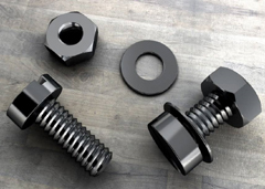
We have many years of experience in the production and sales of screws, nuts, flat washers, etc. The main products are: nut sets, hexagon socket head bolts, hammer head bolts, semi-circle head socket head cap screws and other products, we can provide you with suitable tightening screws for you. Firmware Solutions.


