


 Service Hotline
For hexagonal nuts, the commonly used standards are: GB52, GB6170, GB6172 and DIN934. The main differences between them are: the thickness of GB6170 is thicker than that of GB52, GB6172 and DIN934, commonly known as thick nuts. The other is the difference between the opposite sides, the opposite sides of DIN934, GB6170 and GB6172 in the M8 nut series are 13MM smaller than the opposite side 14MM of GB52, and the opposite sides of M10 nuts, DIN934 and GB52 are 17MM. The opposite side of GB6170 and GB6172 should be 1MM larger, M12 nut, DIN934, GB52's opposite side is 19MM larger than GB6170 and GB6172's opposite side 18MM is 1MM larger. For M14 nuts, the opposite side of DIN934 and GB52 is 22MM, which is 1MM larger than the opposite side of GB6170 and GB6172, which is 21MM. The other is the M22 nut. The opposite side of DIN934 and GB52 is 32MM, which is 2MM smaller than the opposite side of GB6170 and GB6172, which is 34MM. (Besides the thickness of GB6170 and GB6172 are the same, the width of the opposite side is exactly the same) The rest of the specifications can be used in general without considering the thickness.
In machine tool processing, it is often necessary to calibrate and debug the probe. The method of manually correcting the detection is inefficient and the accuracy is unstable. In addition, accidents such as collisions will occur. However, calibration tools such as ring gauges are expensive, have large working strokes and poor versatility. Technical realization elements: In view of the above content, it is necessary to provide a positioning pin for probe calibration to solve the above problems. A positioning pin is used for calibrating a probe, the positioning pin includes a connected cylinder and a cylinder, the cylinder is used to be installed on a jig in a machine tool, and the end of the cylinder away from the cylinder is provided with a measuring hole to calibrate the probe. Further, the positioning pin is also provided with a chip removal hole, one end of the chip removal hole is connected to the measuring hole, the other end of the chip removal hole penetrates the end of the cylinder away from the cylinder, and the chip removal hole is used for discharging machining chips and cutting fluid. Further, the diameter of the chip removal hole is smaller than the diameter of the measuring hole. Further, the positioning pin further includes a positioning piece, the positioning piece includes a base and a magnetic piece, one end of the base is provided with a mounting hole for installing the magnetic piece, and the other end of the base is provided with a limiting hole for mounting the column. Further, the limiting hole communicates with the mounting hole. Further, the limiting hole is a blind hole. Further, the diameter of the cylinder is larger than the diameter of the cylinder. Further, the measuring hole is a cylindrical hole. Further, the diameter of the cylindrical hole is 4 mm. Further, the end face of one end of the cylinder provided with the measuring hole is a curved surface, and the end faces the peripheral wall of the cylinder to bend and transition to connect the peripheral wall. The positioning pin of Guangdong Yueluo Hardware Industry Co., Ltd. uses the measuring hole to carry out the probe. It is easy to operate, simple in structure and highly versatile. BRIEF DESCRIPTION OF THE DRAWINGS FIG. 1 is a perspective view of a positioning pin of an embodiment of Guangdong Yueluo Hardware Industry Co., Ltd. FIG. 2 is a three-dimensional schematic view of the positioning pin shown in FIG. 1 without a positioning member. FIG. 3 is an exploded schematic view of the positioning pin shown in FIG. 1 . FIG. 4 is a cross-sectional view of the positioning pin shown in FIG. 1 along the line IV-IV. Description of main components and symbols Locating pin 100 Cylinder 10 Measuring hole 11 Chip removal hole 12 Cylinder 20 Positioning piece 30 Base 32 Mounting hole 321 Limiting hole 323 Magnetic piece 34 The following specific embodiments will be further described in conjunction with the above drawings Guangdong Yueluo Hardware Industrial Co., Ltd. DETAILED DESCRIPTION OF THE PREFERRED EMBODIMENTS The technical solutions in the embodiments of Guangdong Yueluo Hardware Industry Co., Ltd. will be clearly and completely described below with reference to the accompanying drawings in the embodiments of Guangdong Yueluo Hardware Industry Co., Ltd. Obviously, the described embodiments are only Some examples of Guangdong Yueluo Hardware Industry Co., Ltd. are not all examples. Based on the embodiments in Guangdong Yueluo Hardware Industry Co., Ltd., all other embodiments obtained by those of ordinary skill in the art without creative work belong to the protection scope of Guangdong Yueluo Hardware Industry Co., Ltd. It should be noted that when an element is referred to as being connected to another element, it can be directly connected to the other element or intervening elements may also be present. When an element is referred to as being disposed on another element, it can be directly disposed on the other element or intervening elements may also be present. Unless otherwise defined, all technical and scientific terms used herein are related to those of Guangdong Yueluo Hardware Industry Co., Ltd.
The positioning pin is a pin designed to accurately position the two adjacent parts of the mold in a mold composed of two or more parts. It can be seen that the positioning pin plays a positioning role, and the mold must be accurately synchronized when it is closed. product, and the positioning pin can make the upper and lower molds play a role in accurate positioning. In the mold design and manufacture of Yueluo, the positioning pin is one of the most common parts. Since it is only used for positioning between parts, few people will pay too much attention to it. In the cold stamping process of Yueluo, the dimensional accuracy of the blanking parts depends on the size of the working part of the punch and the concave die, and the dimensional difference between them constitutes the blanking die gap. Gap is an important process parameter for die design, and its size has a great influence on the quality of the section of the blanking part, the blanking force, and the life of the die. If the gap is too large, punching burrs will appear in punching; if the gap is too small, secondary cracks will occur in the section and extrusion burrs will appear, which will make the quality of the section after punching unsatisfactory, and a reasonable gap will not only help the punching section. The improvement of quality also contributes to the improvement of the lifespan of the 9 bottles.
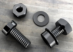
The fixing screw proposed by Guangdong Yueluo Hardware Industry Co., Ltd. has a screw body 1, and the axial surface of the screw body 1 is formed with extending screw teeth 6, and the axial surface is a column along the central axis direction of the cylinder of the screw body 1. The body surface has a hemispherical screw tail 7 at the bottom, and a screw head 2 at the top. The upper surface of the screw head 2 is provided with a slot (not shown). The screw body 1 is composed of the upper tapered rod 4 and the lower cylindrical screw 5. The tapered rod 4 is an inverted cone, the diameter of its circular upper surface and the diameter of the screw mounting hole 10. equal. The fixing screw also has a washer 3, the washer 3 is arranged between the screw head 2 and the screw body 1, the lower surface of the cylindrical washer 3 has a number of teeth 8, the teeth 8 are along the The upper surface of the inverted cone of the tapered rod 4 and the edge of the washer 3 are connected to form a straight convex strip 15 extending outward; the convex strip 15 can also be designed in an arc shape. The fixing screws for installation proposed by Guangdong Yueluo Hardware Industry Co., Ltd. can be made of metal materials in one piece. As shown in Figure 3, it is a schematic diagram of the installation of Guangdong Yueluo Hardware Industry Co., Ltd. for PCB board fixing. When installing, first pass the screw body 1 of the fixing screw through the mounting hole 10 and the copper column 11 provided on the PCB board 9, so that the tail 7 of the screw reaches the mounting hole 13 on the casing 12, and then use the tightening tool 14 to insert the screw At the notch on the top of the head, forcefully press the inverted cone design taper rod 4 of the screw body 1 into the mounting hole 10, so that the tail 7 passes through the mounting hole 13. Due to the outer diameter D at the bottom of the taper rod and the screw mounting hole The aperture size of 10 is equal, and the fixing screws are pressed and fixed, so that the PCB board 9 can be automatically corrected in the process of fixing its front, back, left and right deflections, and the accuracy of the installation position of the PCB board 9 can be ensured. As shown in Figure 4, after the fixing screw is screwed into the casing, the washer 3 is fully contacted and pressed on the PCB board 9, and the PCB board 9, the copper column 11 and the casing 12 are firmly connected together without sliding. . The teeth 8 on the washer 3 are in full contact with the surface of the PCB board 9, so that a ground wire path is set up between the PCB board 9 and the casing 13 by the metal fixing screw 1, thereby ensuring that the PCB board 9 is fully grounded , the design of the teeth 12 on the washer 3 also has a non-slip function. The fixing screws for installation designed by Guangdong Yueluo Hardware Industry Co., Ltd. make use of the cooperation, friction and electrical conductivity in the mechanical connection, which fully guarantees the firm installation of the PCB board and the chassis and the good grounding of the PCB board. Moreover, the ellipsoid tail of the fixing screw The surface is relatively smooth, even if the mounting holes are exposed, it will not cause scratches on the hands and desktop. The above is only the embodiment of Guangdong Yueluo Hardware Industry Co., Ltd., and does not limit the scope of Guangdong Yueluo Hardware Industry Co., Ltd., any equivalent structure made by using the contents of the description and drawings of Guangdong Yueluo Hardware Industry Co., Ltd. or etc. Effective process transformation, or direct or indirect application in other related technical fields, are also included in the protection scope of Guangdong Yueluo Hardware Industry Co., Ltd.
The pin, also known as the pin, has a simple structure and is easy to assemble and disassemble. It is widely used in various fixed connections. The pin is mainly used to fix the relative position between two parts, also used to connect parts, and can transmit a certain load. , At present, the pins on the market generally have the problems of being easy to loosen and fall off.
We have many years of experience in the production and sales of screws, nuts, flat washers, etc. The main products are: cage screws, pressure block nuts, nylon nuts, plastic isolation columns and other products, we can provide you with suitable fastener solutions for you .


