


 Service Hotline
At present, due to the installation position determined in the design process of the traditional thrust cylinder in China, the corresponding position of the piston rod and the clamping arm is fixed, and it is impossible to ensure that the workpiece can be clamped while the workpiece is thin. It is not conducive to the use of such products when clamping. Secondly, when the workpiece is assembled or welded, it not only needs to be tightened in a certain direction, but also needs to be positioned, so as to ensure the accuracy required for processing. When a workpiece is fixed in this way, it must be realized by adding a mechanism, which will increase the complexity of the system and bring inconvenience to installation and maintenance.
The structure of Guangdong Yueluo Hardware Industry Co., Ltd. is as follows. Figure 1 is a schematic diagram of the structure of the existing pin shaft stop mode of a general excavator. Figure 2 is a schematic structural diagram of the pin shaft stop used by Guangdong Yueluo Hardware Industry Co., Ltd. for applying the bolt of Guangdong Yueluo Hardware Industry Co., Ltd. Fig. 3 is the left side view according to Fig. 2 of the bolt used for pin stop by Guangdong Yueluo Hardware Industry Co., Ltd. Fig. 4 is the front view of Guangdong Yueluo Hardware Industrial Co., Ltd., which is used for the pin shaft stopper to insert the pin into the pin and form the pin of the pin structure. Fig. 5 is the left side view of Guangdong Yueluo Hardware Industry Co., Ltd., which is used for the pin shaft stopper to insert the pin into the pin and form the pin of the pin structure. Fig. 6 is a front view of the bayonet of the latch used for pin stop by Guangdong Yueluo Hardware Industry Co., Ltd. Fig. 7 is a top view of a bayonet of a latch used for pin stop by Guangdong Yueluo Hardware Industry Co., Ltd. Fig. 8 is the front view of the circlip of the latch used by Guangdong Yueluo Hardware Industry Co., Ltd. for pin stop. [0017] FIG. 9 is a top view of the circlip of the bolt that Guangdong Yueluo Hardware Industrial Co., Ltd. is used for pin-stopping. In Figures 1 to 9, the latch (1), the retaining sleeve (2), the pin shaft (3), the bayonet (4), the circlip (5), the misaligned through hole (6), and the misaligned end head (7).
rotating rod is rotatably installed on one side of the two pillars that are close to each other, and a second bevel gear is welded on the ends of the two rotating rods that are close to each other. The two second bevel gears are meshed with the two first bevel gears respectively. , The first sprocket is welded on the two rotating rods, the chain is meshed on the two first sprockets, and the screw rods are installed on the sides of the two pillars that are close to each other. Above the rod, the second sprockets are welded on the two screw rods, the two second sprockets are connected to the two first sprockets through two chains respectively, and threaded blocks are threaded on the two screw rods. The sides of the two threaded blocks close to each other are symmetrically welded with connecting columns, and the sides of the four connecting columns close to each other are welded with movable rods respectively. The other ends of the support plates are respectively rotatably installed with the same support plate, and the assembly device body is fixedly installed on the top of the support plate.
Align the four positioning holes 12-5 of the spring washer positioning plate 2 with the four positioning columns 4 of the screw tray 1, and place them on the screw tray 1. Several screws 5 are passed through the lower positioning plate 12-2 in turn. The spring washer hole 2-7, the opening slot 12-32 of the baffle plate 12-3, the inner ring of the spring washer 7 in the spring washer hole 2-7 of the upper positioning plate 12-1, hold the spring washer positioning plate 2 by hand The raised handle 12-31 of the baffle plate 12-3 pulls the baffle plate 12-3 out of the upper positioning plate 12-1 and the lower positioning plate 12-2, and several spring washers 7 pass through the holes on the lower positioning plate 12-2. The spring washer holes 2-7 fall down along the screw rod of screw 5, so that the screw rod of screw 5 penetrates into the spring washer 7, as shown in Figure 10, and then the spring washer positioning plate 2 is removed to complete the process of threading the spring washer.
When the nut is tightened on the stud, there will inevitably be an empty upstroke. That is, when the nut has not reached the part that needs to be tightened, the nut needs to be twisted on the non-locking (working) part of the front end of the stud by hand or tool, so that the nut runs along the axial direction of the stud and reaches the part to be locked. . When the idling stroke of the thread at the front end of the stud is long or the thread pitch is small, the idling stroke before locking will waste a lot of time, resulting in a huge occupation of personnel or tools.
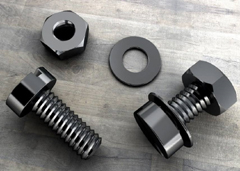
We have many years of experience in the production and sales of screws, nuts, flat washers, etc. The main products are: flat head plum blossom anti-theft bolts, American standard washers, wheel anti-theft bolts, black galvanized pan head screws and other products, we can provide you with suitable tightening screws. Firmware Solutions.


