


 Service Hotline
1. The expansion phenomenon of the spring washer is generally not the problem of the spring washer itself. 2. The spring washer with the expansion ring must be subjected to a radial external tension. The external tension is derived from the tightening axial force generated by the tightening torque. The chamfer creates a radial component of the axial clamping force, which expands the opening of the spring washer. The smaller the chamfer diameter, the greater the possibility of ring expansion. 4. Adding a flat washer between the nut and the spring washer helps to slow down or prevent the expansion of the ring, but the flat washer is too thin or too soft. Prevent ring expansion 5. The reason for the hydrogen embrittlement fracture of spring washers is generally due to unreasonable heat treatment process and the failure of hydrogen removal treatment after electro-galvanizing. A large number of tests and long-term practical experience have confirmed the above analysis.
Heat treatment broadcast quenching and tempering HB220-270, nitriding HRC>65 foreign use titanium carbide coating method to improve the corrosion resistance of the screw surface, but according to reports, its wear resistance is not good enough. A series of measures have been taken abroad to improve the wear resistance and corrosion resistance of the screw. One way is to use highly wear-resistant and corrosion-resistant alloy steel. Such as 34CrAlNi, 31CrMo12 and so on. There is also a method of spraying Xaloy alloy on the surface of the screw. This Xaloy alloy has high wear and corrosion resistance.
In another embodiment of Guangdong Yueluo Hardware Industry Co., Ltd., the slotting device 4 includes a motor 41 and a motor 43, the cutting wheel 42 is fixedly arranged at the output end of the motor 41, and the motor 41 drives the cutting wheel 42 to rotate to open the screw. slot, the motor 43 is fixedly arranged on the workbench 1, the motor 41 is arranged on the motor 43, a track 47 is arranged between the motor 41 and the motor 43, the motor 41 can reciprocate through the track 47, and when the screw is slotted, the motor 41 drives the cutting wheel 42 to move in the direction of the screw. When the slotting is finished, the motor 41 drives the cutting wheel 42 to retract. The fixed wheel 48 is arranged at the output end of the motor 43. The fixed wheel 48 is located directly below the cutting wheel 42. The surface of the middle screw is in contact, and the motor 43 drives the fixed wheel 48 to rotate to grind and polish the surface of the slotted screw to make the surface smooth. Preferably, the direction of rotation of the cutting wheel 42 and the fixed wheel 48 is opposite.
In the design of modern aviation and aerospace vehicles, in order to reduce weight and save space, the space of the fastening installation system is getting narrower and narrower, and blind hole installation is often required. In this case, single-sided riveting installation is usually used for fastening connection. At present, this kind of fastening connection products are mainly blind rivets. The riveting installation principle of blind rivets is to use the method of pulling, pulling the mandrel, and extruding the nail sleeve to deform it at the blind end to achieve the function of fastened connection. This kind of fastening connection method requires special riveting, generally imported riveting, the replacement of internal parts is expensive, the installation process is complicated, and the installation cost is high.
The existing way to achieve radial locking of the shaft is generally to sleeve the positioning block on the shaft, and then use a cylindrical pin to pass through the positioning block to lock the shaft. The locking structure and method are as follows: A locking groove with an arc-shaped cross-section is set on the outer side of the shaft along the direction perpendicular to the axis of the shaft, an opening is set on the positioning block, and then a cylindrical pin is used to pass through the positioning block from the outside of the positioning block and screw the lock at one end of the cylindrical pin. When the lock nut is tightened, the opening on the positioning block will be deformed inwardly and locked on the shaft.
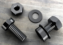
We have many years of experience in the production and sales of screws, nuts, flat washers, etc. The main products are: flange silicone washers, hinge bolts, square nuts, flange screws and other products, we can provide you with suitable fasteners for you solution.


