


What is the tolerance range of precision screws?
What is the tolerance range of precision screws?
Service Hotline
+86760-8787 8587We have more than ten years of production experience in the screw industry, the main products are: non-standard metal flat washers, pull-out screws, brass male screws, hexagon bolts, dome head round cup screws, square coupling gasket manufacturers, round head cross Screw nuts, metal galvanized bolts, explosive screws, open countersunk head rivets, ISO7380 screws, GB819 fastened countersunk head bolts, 62 copper bolts, flat and thin screw caps, positive national standard screws and other fasteners, due to the different materials and specifications of the products Different, the price is also different, if you need, please contact us.


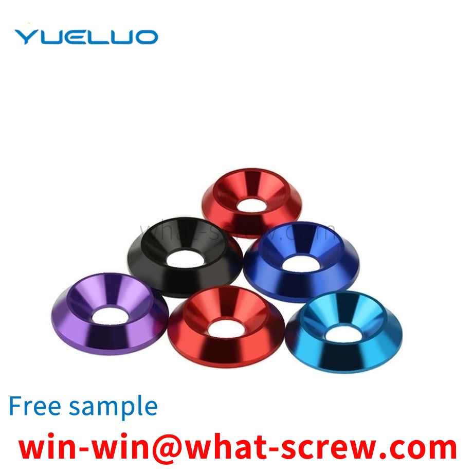
Gaskets are divided into: flat washer - grade C, large washer - grade A and C, extra large washer - grade C, small washer - grade A, flat washer - grade A, flat washer - chamfer type - Grade A, high-strength washers for steel structure, spherical washers, cone washers, square bevel washers for I-beam, square bevel washers for channel steel, standard spring washers, light spring washers, heavy spring washers, internal tooth lock washers , Internal serrated lock washers, external serrated lock washers, external serrated lock washers, single-ear stop washers, double-ear stop washers, outer tongue stop washers and stop washers for round nuts, etc.

Most of the existing screws use an integral metal structure, and there are still some problems, such as large weight, high cost of materials, wear resistance, hardness, rust resistance, corrosion resistance, high and low temperature resistance, brittleness, toughness, etc. Many occasions cannot meet the needs of production, and further improvements are needed to improve production efficiency, reduce costs, improve safety, and prolong the service life of screws.


High-strength bolt connection has the advantages of simple construction, good mechanical performance, disassembly and replacement, fatigue resistance, and no loosening under dynamic load. It is a promising connection method. High-strength bolts use a special wrench to tighten the nut, so that the bolt generates a huge and controlled pre-tension. Under the action of pre-pressure, a large frictional force will be generated along the surface of the connected parts. Obviously, as long as the axial force is less than this frictional force, the components will not slip and the connection will not be damaged. This is the high-strength bolt connection. principle. High-strength bolted connections rely on the friction between the contact surfaces of the connectors to prevent them from sliding each other. In order to make the contact surfaces have sufficient friction, it is necessary to increase the clamping force of the components and increase the friction coefficient of the contact surfaces of the components. The clamping force between the components is achieved by applying pretension to the bolts, so the bolts must be made of high-strength steel, which is why it is called high-strength bolted connections. In high-strength bolted connections, the friction coefficient has a great influence on the bearing capacity. Tests show that the coefficient of friction is mainly affected by the form of the contact surface and the material of the components. In order to increase the friction coefficient of the contact surface, methods such as sandblasting and wire brush cleaning are often used to treat the contact surface of the components within the connection range during construction.

In machine tool processing, it is often necessary to calibrate and debug the probe. The method of manually correcting the detection is inefficient and the accuracy is unstable. In addition, accidents such as collisions will occur. However, calibration tools such as ring gauges are expensive, have large working strokes and poor versatility. Technical realization elements: In view of the above content, it is necessary to provide a positioning pin for probe calibration to solve the above problems. A positioning pin is used for calibrating a probe, the positioning pin includes a connected cylinder and a cylinder, the cylinder is used to be installed on a jig in a machine tool, and the end of the cylinder away from the cylinder is provided with a measuring hole to calibrate the probe. Further, the positioning pin is also provided with a chip removal hole, one end of the chip removal hole is connected to the measuring hole, the other end of the chip removal hole penetrates the end of the cylinder away from the cylinder, and the chip removal hole is used for discharging machining chips and cutting fluid. Further, the diameter of the chip removal hole is smaller than the diameter of the measuring hole. Further, the positioning pin further includes a positioning piece, the positioning piece includes a base and a magnetic piece, one end of the base is provided with a mounting hole for installing the magnetic piece, and the other end of the base is provided with a limiting hole for mounting the column. Further, the limiting hole communicates with the mounting hole. Further, the limiting hole is a blind hole. Further, the diameter of the cylinder is larger than the diameter of the cylinder. Further, the measuring hole is a cylindrical hole. Further, the diameter of the cylindrical hole is 4 mm. Further, the end face of one end of the cylinder provided with the measuring hole is a curved surface, and the end faces the peripheral wall of the cylinder to bend and transition to connect the peripheral wall. The positioning pin of Guangdong Yueluo Hardware Industry Co., Ltd. uses the measuring hole to carry out the probe. It is easy to operate, simple in structure and highly versatile. BRIEF DESCRIPTION OF THE DRAWINGS FIG. 1 is a perspective view of a positioning pin of an embodiment of Guangdong Yueluo Hardware Industry Co., Ltd. FIG. 2 is a three-dimensional schematic view of the positioning pin shown in FIG. 1 without a positioning member. FIG. 3 is an exploded schematic view of the positioning pin shown in FIG. 1 . FIG. 4 is a cross-sectional view of the positioning pin shown in FIG. 1 along the line IV-IV. Description of main components and symbols Locating pin 100 Cylinder 10 Measuring hole 11 Chip removal hole 12 Cylinder 20 Positioning piece 30 Base 32 Mounting hole 321 Limiting hole 323 Magnetic piece 34 The following specific embodiments will be further described in conjunction with the above drawings Guangdong Yueluo Hardware Industrial Co., Ltd. DETAILED DESCRIPTION OF THE PREFERRED EMBODIMENTS The technical solutions in the embodiments of Guangdong Yueluo Hardware Industry Co., Ltd. will be clearly and completely described below with reference to the accompanying drawings in the embodiments of Guangdong Yueluo Hardware Industry Co., Ltd. Obviously, the described embodiments are only Some examples of Guangdong Yueluo Hardware Industry Co., Ltd. are not all examples. Based on the embodiments in Guangdong Yueluo Hardware Industry Co., Ltd., all other embodiments obtained by those of ordinary skill in the art without creative work belong to the protection scope of Guangdong Yueluo Hardware Industry Co., Ltd. It should be noted that when an element is referred to as being connected to another element, it can be directly connected to the other element or intervening elements may also be present. When an element is referred to as being disposed on another element, it can be directly disposed on the other element or intervening elements may also be present. Unless otherwise defined, all technical and scientific terms used herein are related to those of Guangdong Yueluo Hardware Industry Co., Ltd.

The above content is uploaded by Yueluo or the Internet. If there is any copyright issue, please contact [email protected].
What is the tolerance range of precision screws?

How to choose the right stainless steel screw manufacturer?

Why is there an R angle under the head of the hexagon head s...

We have more than ten years of production experience in the ...
We have more than ten years of experience in the production ...

We have more than ten years of experience in the production ...

We have more than ten years of experience in screw industry ...

+86760-8787 8587

+86132 6870 6820

mobile website

+86760-22181790

