


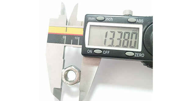
What is the tolerance range of precision screws?
What is the tolerance range of precision screws?
Service Hotline
+86760-8787 8587We have more than ten years of experience in screw industry production, the main products are: IN949 stud bolts, GB856 gaskets, headless hexagon socket head bolts, knurled cylinder head bolts, Yueluo production of non-standard nuts, single-way nuts, wood handle screws, Oblique large flat head bolts, titanium spring washers, countersunk head slotted screws, DIN931 screws, metric plug screws, practical connector square nuts, flat head screws, 1 spot welding nuts and other fasteners, due to the different materials and specifications of the products. There are different prices, please contact us if necessary.


screw locking device includes a mounting frame, a driving structure arranged on the mounting frame, a screwdriver and a measuring structure driven and moved by the driving structure; the measuring structure includes a solenoid valve cylinder, which is fixedly connected with a piston rod of the solenoid valve cylinder. The ejector rod, the pressure sensor for detecting the thrust of the solenoid valve cylinder, and the control panel electrically connected with the driving structure, the solenoid valve and the pressure sensor.

The positioning pin is a pin designed to accurately position the two adjacent parts of the mold in a mold composed of two or more parts. It can be seen that the positioning pin plays a positioning role, and the mold must be accurately synchronized when it is closed. product, and the positioning pin can make the upper and lower molds play a role in accurate positioning. In the mold design and manufacture of Yueluo, the positioning pin is one of the most common parts. Since it is only used for positioning between parts, few people will pay too much attention to it. In the cold stamping process of Yueluo, the dimensional accuracy of the blanking parts depends on the size of the working part of the punch and the concave die, and the dimensional difference between them constitutes the blanking die gap. Gap is an important process parameter for die design, and its size has a great influence on the quality of the section of the blanking part, the blanking force, and the life of the die. If the gap is too large, punching burrs will appear in punching; if the gap is too small, secondary cracks will occur in the section and extrusion burrs will appear, which will make the quality of the section after punching unsatisfactory, and a reasonable gap will not only help the punching section. The improvement of the quality also contributes to the improvement of the lifespan of the 6-pack.


The existing welding stud only has one welding spot on the top surface of the screw head, and the welding stud is relatively long and thick. When welding, the current will be relatively large, so that all the welding spots can be melted to complete the welding process. Because there is only one welding spot, and the welding stud is relatively long and thick, the increase of the current during welding will deform the melting point of the metal plate, which will lead to the penetration of the metal plate, which will lead to the concave and convex welding scars on the back of the welded plate, which will affect the appearance. Only one welding spot is located to be welded with the metal plate. During welding, the uneven parallelism of one spot leads to insufficient stability and a certain slope. It is easy for workers to have insufficient stability and parallelism when operating, resulting in wasted time and high scrap rate. increase.

In another embodiment of Guangdong Yueluo Hardware Industry Co., Ltd., the slotting device 4 includes a motor 41 and a motor 43, the cutting wheel 42 is fixedly arranged at the output end of the motor 41, and the motor 41 drives the cutting wheel 42 to rotate to open the screw. slot, the motor 43 is fixedly arranged on the workbench 1, the motor 41 is arranged on the motor 43, a track 47 is arranged between the motor 41 and the motor 43, the motor 41 can reciprocate through the track 47, and when the screw is slotted, the motor 41 drives the cutting wheel 42 to move in the direction of the screw. When the slotting is finished, the motor 41 drives the cutting wheel 42 to retract. The fixed wheel 48 is arranged at the output end of the motor 43. The fixed wheel 48 is located directly below the cutting wheel 42. The surface of the middle screw is in contact, and the motor 43 drives the fixed wheel 48 to rotate to grind and polish the surface of the slotted screw to make the surface smooth. Preferably, the direction of rotation of the cutting wheel 42 and the fixed wheel 54 is opposite.

The above content is uploaded by Yueluo or the Internet. If there is any copyright issue, please contact [email protected].
What is the tolerance range of precision screws?

How to choose the right stainless steel screw manufacturer?

Why is there an R angle under the head of the hexagon head s...

We have more than ten years of production experience in the ...
We have more than ten years of experience in the production ...

We have more than ten years of experience in the production ...

We have more than ten years of experience in screw industry ...

+86760-8787 8587

+86132 6870 6820

mobile website

+86760-22181790

