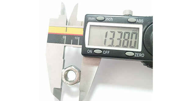
What is the tolerance range of precision screws?
What is the tolerance range of precision screws?
Service Hotline
+86760-8787 8587We have more than ten years of production experience in the screw industry, the main products are: solid pressure rivets, slotted cylinder head screws, combination set screws and nuts, butterfly spring washers, rear clamp nut blocks, iron GB867 rivets, thick nuts, Photo album butt screws, anti-skid washers, stainless steel bolts, lock cylindrical positioning pins, decorative nuts, lighting accessories hexagon nuts, mother-in-law nails, DIN6925 hexagon lock nuts and other fasteners, due to different product materials and specifications, the price is also different, please contact us if necessary.


Two combination screws are mostly used for the connection between thin metal plates, and play a connecting role. When connecting, first make a threaded bottom hole for the connected piece, and then screw the combination screw into the threaded bottom hole of the connected piece. Since the threaded surface of the combination screw has high hardness, the inner thread can be tapped in the threaded bottom hole of the connected piece to form a connection.

Knurled copper nuts are widely used in the following fields: notebook computer plastic casing, desktop computer plastic casing, GPS plastic casing, router plastic casing, mobile phone plastic casing, infinite communication facility plastic casing, home appliance plastic casing, automobile, electrical appliances, medical, electronics, etc. plastic shell.


At present, for roller or needle roller bearings without cages, ribs, and low-speed operation, the structure mainly includes inner and outer rings and rollers or needle rollers in the raceway between the inner and outer rings, and additional The retaining rings on both sides of the roller or needle roller, among which the retaining rings added on both sides of the roller or needle roller are annular steel sheets punched from metal sheet, and their function in the bearing is only Correctly guide the rollers or needle rollers to run normally in the raceway between the inner and outer rings to prevent the rollers or needle rollers from deviating and slipping out of the raceway. The defect of the retaining ring of this structure is that first, because the rigid retaining ring and the inner ring are completely separated, there is a gap between the retaining ring and the installation shaft during installation. When the bearing is working, The retaining ring is driven by the outer ring and the rollers or needle rollers to rotate around the installation shaft. Due to the inconsistency of the structure, the retaining ring is easy to fall off during the rotation process, the safety of use is poor, and the rollers or needle rollers will appear toward the raceway. The situation of one side offset, which causes the bearing load center to offset, affects the reliability of the bearing operation, and ultimately affects the service life of the bearing; There is a gap between the raceways of the needle, so the tidbits, dust, etc. generated during the working process will continue to enter the raceway between the inner and outer rings. It is stuck; in addition, due to the gap between the steel retaining ring and the raceway, the grease stored in the raceway will be continuously lost, which will cause the bearing to heat up due to frequent lack of grease, or even burn out, which also affects the to the service life of the bearing.

The conventional auger bit structure 1 includes a rod body 11, a screw head 12 provided on one end of the rod body 11, a drill tail 13 provided on the other end of the rod body 11, and a plurality of threads 14 arranged around the rod body 11; Wherein, the periphery of the drill tail 13 defines a parting line 15, and the parting line 15 makes the drill tail 13 symmetrically divided into a side 131 and a side 132, and a cutting end 133 is formed at the junction of the end of the side 131 and the end of the side 132, respectively. The cutting end 133 is concavely provided with a quarter-turn chip flute 134 in the same direction of the helix, and the edge 132 continues the chip flute 134 and has a quarter-turn chip flute 135 with different helical curvatures. , by connecting the chip groove 134 and the chip groove 135 through different helical curvatures, the drill tail 13 can form a symmetrical and complete chip groove of 188 degrees.

The above content is uploaded by Yueluo or the Internet. If there is any copyright issue, please contact [email protected].

What is the tolerance range of precision screws?

How to choose the right stainless steel screw manufacturer?

Why is there an R angle under the head of the hexagon head s...

We have more than ten years of production experience in the ...

We have more than ten years of experience in the production ...

We have more than ten years of experience in the production ...

We have more than ten years of experience in screw industry ...