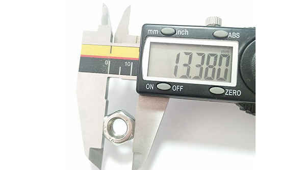
What is the tolerance range of precision screws?
What is the tolerance range of precision screws?
Service Hotline
+86760-8787 8587We have more than ten years of experience in screw industry production, the main products are: anti-loose and anti-skid self-locking nut with pad, internal and external sawtooth anti-skid, national standard aluminum T-nut, precision machining, GB812 slotted round nut, thread bar screw, Metal mesons, flange screws, ring screws, unrolled cup head screws, nickel-plated and hardened, camera bracket conversion extension screws and nuts, injection knurled nuts, knurled cup head screws, single-head hexagonal studs, etc. Firmware, due to different product materials and specifications, the price is also different, please contact us if necessary.


The fixing screw proposed by Guangdong Yueluo Hardware Industry Co., Ltd. has a screw body 1, and the axial surface of the screw body 1 is formed with extending screw teeth 6, and the axial surface is a column along the central axis direction of the cylinder of the screw body 1. The body surface has a hemispherical screw tail 7 at the bottom, and a screw head 2 at the top. The upper surface of the screw head 2 is provided with a slot (not shown). The screw body 1 is composed of the upper tapered rod 4 and the lower cylindrical screw 5. The tapered rod 4 is an inverted cone, the diameter of its circular upper surface and the diameter of the screw mounting hole 10. equal. The fixing screw also has a washer 3, the washer 3 is arranged between the screw head 2 and the screw body 1, the lower surface of the cylindrical washer 3 has a number of teeth 8, the teeth 8 are along the The upper surface of the inverted cone of the tapered rod 4 and the edge of the washer 3 are connected to form a straight convex strip 15 extending outward; the convex strip 15 can also be designed in an arc shape. The fixing screws for installation proposed by Guangdong Yueluo Hardware Industry Co., Ltd. can be made of metal materials in one piece. As shown in Figure 3, it is a schematic diagram of the installation of Guangdong Yueluo Hardware Industry Co., Ltd. for PCB board fixing. When installing, first pass the screw body 1 of the fixing screw through the mounting hole 10 and the copper column 11 provided on the PCB board 9, so that the tail 7 of the screw reaches the mounting hole 13 on the casing 12, and then use the tightening tool 14 to insert the screw At the notch on the top of the head, forcefully press the inverted cone design taper rod 4 of the screw body 1 into the mounting hole 10, so that the tail 7 passes through the mounting hole 13. Due to the outer diameter D at the bottom of the taper rod and the screw mounting hole The aperture size of 10 is equal, and the fixing screws are pressed and fixed, so that the PCB board 9 can be automatically corrected in the process of fixing its front, back, left and right deflections, and the accuracy of the installation position of the PCB board 9 can be ensured. As shown in Figure 4, after the fixing screw is screwed into the casing, the washer 3 is fully contacted and pressed on the PCB board 9, and the PCB board 9, the copper column 11 and the casing 12 are firmly connected together without sliding. . The teeth 8 on the washer 3 are in full contact with the surface of the PCB board 9, so that a ground wire path is set up between the PCB board 9 and the casing 13 by the metal fixing screw 1, thereby ensuring that the PCB board 9 is fully grounded , the design of the teeth 13 on the washer 3 also has a non-slip function. The fixing screws for installation designed by Guangdong Yueluo Hardware Industry Co., Ltd. make use of the cooperation, friction and electrical conductivity in the mechanical connection, which fully guarantees the firm installation of the PCB board and the chassis and the good grounding of the PCB board. Moreover, the ellipsoid tail of the fixing screw The surface is relatively smooth, even if the mounting holes are exposed, it will not cause scratches on the hands and desktop. The above is only the embodiment of Guangdong Yueluo Hardware Industry Co., Ltd., and does not limit the scope of Guangdong Yueluo Hardware Industry Co., Ltd., any equivalent structure made by using the contents of the description and drawings of Guangdong Yueluo Hardware Industry Co., Ltd. or etc. Effective process transformation, or direct or indirect application in other related technical fields, are also included in the protection scope of Guangdong Yueluo Hardware Industry Co., Ltd.
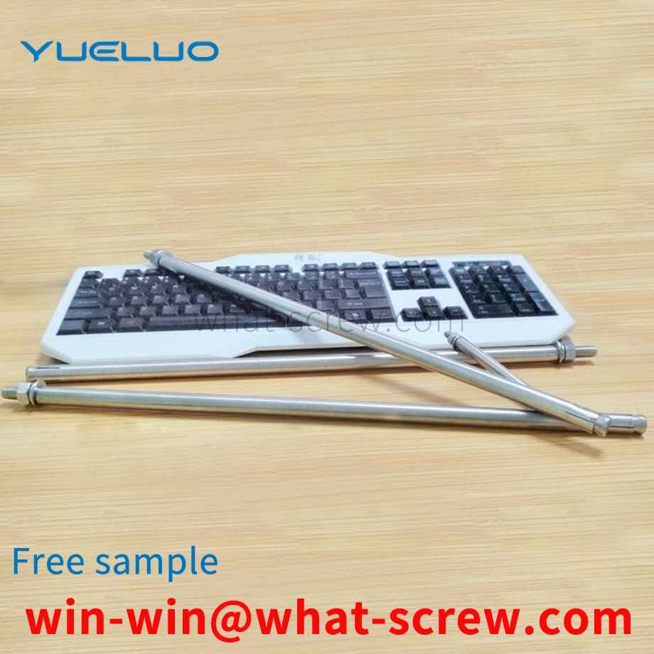
The production of stud bolts requires fixed equipment and machine tool processing. Of course, the processing procedure is relatively simple. There are mainly the following procedures: first, the material needs to be pulled out. After this process, the next process can be carried out. The next process is to use a cutting machine to cut the straight and long material into the length required by the customer according to the customer's requirements. This completes the second process. The third process is Put the cut short material on the thread rolling machine and roll out the thread; the ordinary stud bolts are processed here, of course, if other requirements are required, other processes are required. [1] The commonly known bolt refers to the screw with a larger diameter. According to this statement, the diameter of the screw is much smaller than that of the bolt. Stud bolts do not have a head, and some are called studs. Both ends of the stud are threaded, with no thread in the middle and a smooth rod in the middle. Studs are used on large equipment such as gear racks. In actual use, the external load will have vibration and the influence of temperature will reduce the frictional force, and the threaded connection will loosen and fail over time. Therefore, it is necessary to do a good job in the maintenance of the stud bolts at ordinary times. Stud bolts or anchor bolts will have problems under the action of mechanical friction for a long time. When problems occur, the engine oil pan should be removed, and the use of the engine bearing bushes should be carefully checked, and the clearance between the bearing bushes should be checked. Whether it is too large, if the gap is too large, it should be replaced in time. When replacing the stud bolts, also replace the connecting rod bolts. When some large equipment such as nail making machines are in normal operation, if they find that the engine is not running very stable or there is abnormal noise, they should stop and check in time to avoid bigger problems. [1] In each maintenance, the newly replaced stud bolts and other accessories should be inspected. During the inspection, the focus should be on the head and guide part of the stud bolt. Whether there are cracks or dents in each part, and also check whether the tooth shape of the stud bolt has changed. Is there any abnormality in the thread pitch? If there is any abnormality, it must not be used again. A torque wrench should be used when installing the connecting rod cover. It must be tightened according to the specified standards, the torque should not be too large or too small, and attention should be paid to selecting the stud bolts and studs of the supporting manufacturer.
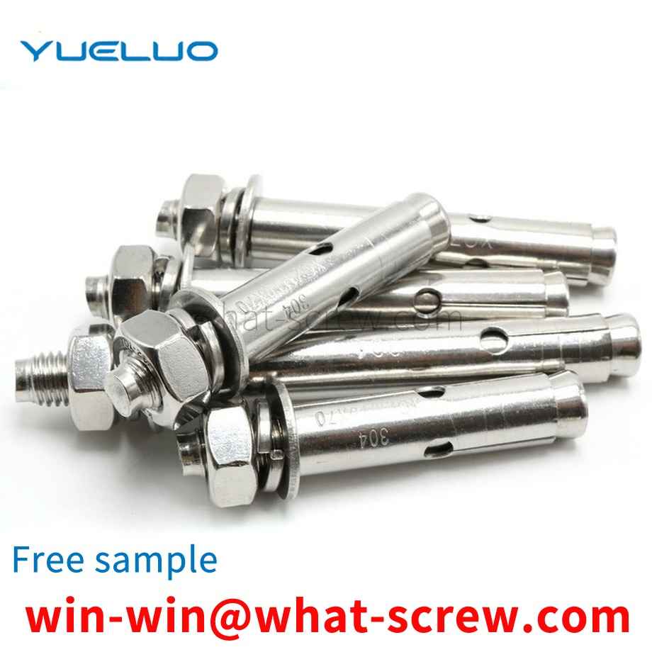
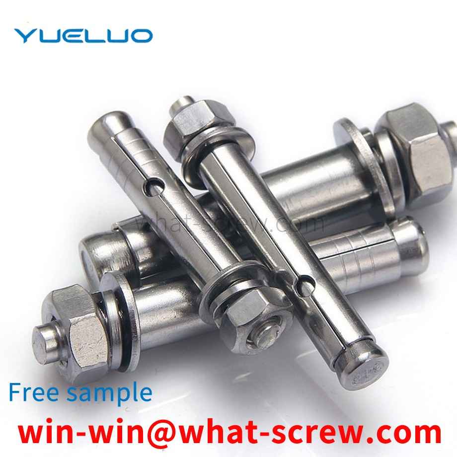
The conventional auger bit structure 1 includes a rod body 11, a screw head 12 provided on one end of the rod body 11, a drill tail 13 provided on the other end of the rod body 11, and a plurality of threads 14 arranged around the rod body 11; Wherein, the periphery of the drill tail 13 defines a parting line 15, and the parting line 15 makes the drill tail 13 symmetrically divided into a side 131 and a side 132, and a cutting end 133 is formed at the junction of the end of the side 131 and the end of the side 132, respectively. The cutting end 133 is concavely provided with a quarter-turn chip flute 134 in the same direction of the helix, and the edge 132 continues the chip flute 134 and has a quarter-turn chip flute 135 with different helical curvatures. , by connecting the chip groove 134 and the chip groove 135 through different helical curvatures, the drill tail 13 can form a symmetrical and complete chip groove of 188 degrees.
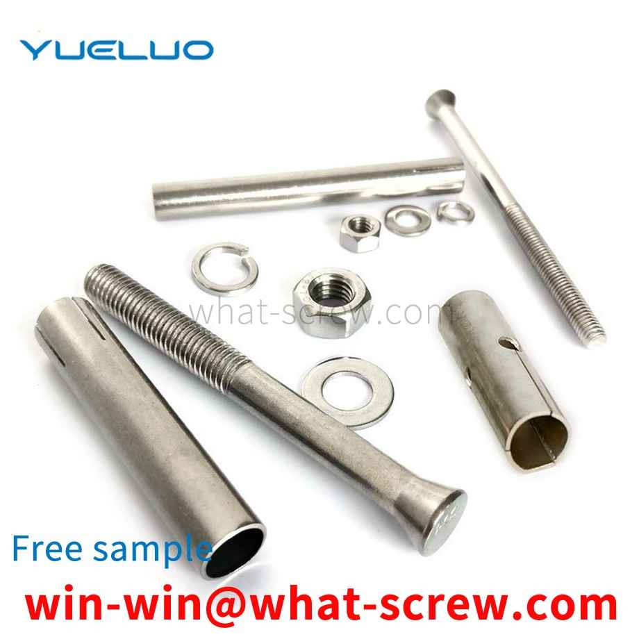
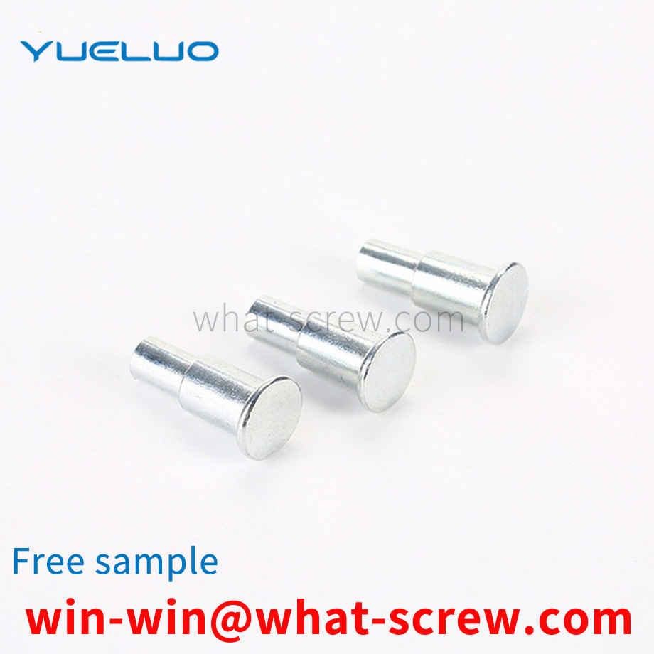
As the requirements for the use of electrical appliances in various industries continue to increase, the testing specifications for the performance of various components in electrical appliances are also constantly improving. Riveted contact elements are used in various relays, contactors, small switches, thermostats, etc. in low-voltage electrical appliances. The structure of the riveted contact element generally includes a contact base and a rivet riveted to the contact base. The rivet includes a rivet head and a rivet top, the structure of which is shown in FIG. 1 .
The above content is uploaded by Yueluo or the Internet. If there is any copyright issue, please contact [email protected].
What is the tolerance range of precision screws?

How to choose the right stainless steel screw manufacturer?

Why is there an R angle under the head of the hexagon head s...
We have more than ten years of screw industry production exp...

We have more than ten years of experience in the production ...

We have more than ten years of production experience in the ...
We have more than ten years of production experience in the ...