


 Service Hotline
1. For low strength (below 500 N/mm2 or below 60000 psi) bolts use general soft steel, generally use SAE 1008 or JIS SWRM 8 (or SWRCH 8). 2. Lower strength (600 N/mm2 or 74000 psi) ) bolts use general soft steel, but limited carbon content grade, generally use SAE 1010 - 1015 or JIS SWRM 10 - 15 (or SWRCH 10 - 15). .3. Higher strength ( 800 N/mm2 or 125000 psi ) bolts of medium carbon steel, low carbon boron steel plus quenching and tempering, generally use SAE 1035 - 1040 or SWRCH 35K - 40K. 4. High strength (900 N/mm2 or more or 150000 psi or more) bolts use medium carbon Alloy steel or low carbon boron steel, in terms of application, if the metric Class 10.9 uses low carbon boron steel, the imprint should be added under the series imprint to become 10.9, and the imprint of the inch 8.2 grade is also used with the general Grade 8 bolts The imprint is different for easy identification. High-strength bolts made of low carbon boron steel cannot be used in high temperature conditions. The design strength exceeds Class 12.9 or ASTM A574 ultra-high strength bolts are limited to medium carbon alloy steel plus quenching and tempering. The performance grades of bolts for steel structure connection are divided into more than 10 grades such as 3.6, 4.6, 4.8, 5.6, 6.8, 8.8, 9.8, 10.9, 12.9, etc. Among them, the bolts of grade 8.8 and above are made of low-carbon alloy steel or medium-carbon steel and are heat-treated (quenching, tempering), commonly known as high-strength bolts, the rest are commonly known as ordinary bolts. The bolt performance grade label consists of two parts of numbers, which represent the nominal tensile strength value and yield ratio of the bolt material respectively. For example, a bolt with a performance level of 4.6 means: 1. The nominal tensile strength of the bolt material is 400MPa; 2. The yield ratio of the bolt material is 0.6; 3. The nominal yield strength of the bolt material is 400×0.6=240Mpa . Performance level 10.9 high-strength bolts, after heat treatment, can achieve: 1. The nominal tensile strength of the bolt material is 1000MPa; 2. The yield ratio of the bolt material is 0.9; High-strength bolts, processing and manufacturing problems are compared Small, general fastener manufacturing companies can master the manufacturing process; but problems are prone to occur in material selection and heat treatment. Material selection is the primary link. Various alloying elements have a great influence on the properties of the material, and the material must be subjected to spectral composition analysis; secondly, the fracture problem and the choice of heat treatment process have a great influence and are very important. Dealers and traders must control the inspection and performance testing links; automotive fasteners have high requirements and must carefully control the quality.
The capped nut can prevent the bolt connection from directly contacting with the outside world, which is corroded and makes it difficult to disassemble later. Nuts with caps in the prior art are mostly of one-piece structure, and the surface is not treated with anti-oxidation, which is easy to be corroded. In addition to the protective effect, the fastening method is the same as that of ordinary nuts, so it is easy to loosen when subjected to severe vibration. .
In machine tool processing, it is often necessary to calibrate and debug the probe. The method of manually correcting the detection is inefficient and the accuracy is unstable. In addition, accidents such as collisions will occur. However, calibration tools such as ring gauges are expensive, have large working strokes and poor versatility. Technical realization elements: In view of the above content, it is necessary to provide a positioning pin for probe calibration to solve the above problems. A positioning pin is used for calibrating a probe, the positioning pin includes a connected cylinder and a cylinder, the cylinder is used to be installed on a jig in a machine tool, and the end of the cylinder away from the cylinder is provided with a measuring hole to calibrate the probe. Further, the positioning pin is also provided with a chip removal hole, one end of the chip removal hole is connected to the measuring hole, the other end of the chip removal hole penetrates the end of the cylinder away from the cylinder, and the chip removal hole is used for discharging machining chips and cutting fluid. Further, the diameter of the chip removal hole is smaller than the diameter of the measuring hole. Further, the positioning pin further includes a positioning piece, the positioning piece includes a base and a magnetic piece, one end of the base is provided with a mounting hole for installing the magnetic piece, and the other end of the base is provided with a limiting hole for mounting the column. Further, the limiting hole communicates with the mounting hole. Further, the limiting hole is a blind hole. Further, the diameter of the cylinder is larger than the diameter of the cylinder. Further, the measuring hole is a cylindrical hole. Further, the diameter of the cylindrical hole is 4 mm. Further, the end face of one end of the cylinder provided with the measuring hole is a curved surface, and the end faces the peripheral wall of the cylinder to bend and transition to connect the peripheral wall. The positioning pin of Guangdong Yueluo Hardware Industry Co., Ltd. uses the measuring hole to carry out the probe. It is easy to operate, simple in structure and highly versatile. BRIEF DESCRIPTION OF THE DRAWINGS FIG. 1 is a perspective view of a positioning pin of an embodiment of Guangdong Yueluo Hardware Industry Co., Ltd. FIG. 2 is a three-dimensional schematic view of the positioning pin shown in FIG. 1 without a positioning member. FIG. 3 is an exploded schematic view of the positioning pin shown in FIG. 1 . FIG. 4 is a cross-sectional view of the positioning pin shown in FIG. 1 along the line IV-IV. Description of main components and symbols Locating pin 100 Cylinder 10 Measuring hole 11 Chip removal hole 12 Cylinder 20 Positioning piece 30 Base 32 Mounting hole 321 Limiting hole 323 Magnetic piece 34 The following specific embodiments will be further described in conjunction with the above drawings Guangdong Yueluo Hardware Industrial Co., Ltd. DETAILED DESCRIPTION OF THE PREFERRED EMBODIMENTS The technical solutions in the embodiments of Guangdong Yueluo Hardware Industry Co., Ltd. will be clearly and completely described below with reference to the accompanying drawings in the embodiments of Guangdong Yueluo Hardware Industry Co., Ltd. Obviously, the described embodiments are only Some examples of Guangdong Yueluo Hardware Industry Co., Ltd. are not all examples. Based on the embodiments in Guangdong Yueluo Hardware Industry Co., Ltd., all other embodiments obtained by those of ordinary skill in the art without creative work belong to the protection scope of Guangdong Yueluo Hardware Industry Co., Ltd. It should be noted that when an element is referred to as being connected to another element, it can be directly connected to the other element or intervening elements may also be present. When an element is referred to as being disposed on another element, it can be directly disposed on the other element or intervening elements may also be present. Unless otherwise defined, all technical and scientific terms used herein are related to those of Guangdong Yueluo Hardware Industry Co., Ltd.
kind of screw provided by Yueluo, the rod body of the screw rod has a thread segment, one end of the thread segment is provided with an annular convex ring on the outer peripheral surface of the rod body, and the distance between the convex ring at the front end of the screw threading direction and the rod core Smaller than the nominal size of the threaded section or the distance from the rear end of the bead to the rod core in the screwing direction is greater than the nominal size of the threaded section.
In the current production process, the inner wall of the circlip is quantitatively and evenly lubricated, and then the rotating shaft is inserted into the circlip, so that the rotating axis can rotate in the circlip, thereby realizing the rotation function of the sun visor. However, since the circlip is tightly fitted with the rotating shaft, during the insertion process of the rotating shaft, the front end of the circlip can easily push the grease from the opening at one end of the circlip to the opening on the other end of the circlip, so that the rotating axis and the inner wall of the circlip are easily connected. There is little or no grease left between them, which can easily lead to a lack of lubrication between the shaft and the circlip, and dry friction between the shaft and the circlip, resulting in a series of problems such as abnormal noise, difficult operation, and poor durability.
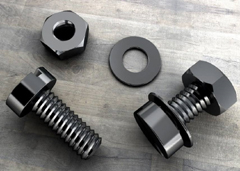
We have many years of experience in the production and sales of screws, nuts, flat washers, etc. The main products are: GB882 pin shaft flat head cylindrical pin with hole, aluminum pull rivet, hexagonal isolation column, hardened iron countersunk head internal and external teeth nuts and other products, we can provide You have the right fastener solution for you.


